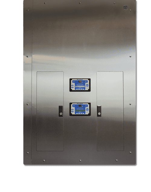
The single transformer voltage isolated power panel is a single panel allowing a primary feed to drive two separate output voltages from a single transformer and a 12” back box for all depths with a concealed hinged front. This configuration provides up to sixteen 120V, 20A circuits for standard line-powered equipment and up to two 208 or 240V, 30 or 50A dedicated circuits for laser equipment loads. The IPD Panel is a cost-effective alternative for providing high voltage output without an additional dedicated primary feed and the premier power panel for laser applications.
Panel Sizing
|
kVA Size |
Back Box Size |
|
|
10 |
5 |
|
|
10 |
7.5 |
|
|
10 |
10 |
|
|
15 |
7.5 |
|
|
15 |
10 |
|
Select from available combinations for high and low voltages (ex. 10kVA at 208V high-side and 7.5kVA at 120V low-side).
- The kVA of the panel transformer is determined by adding together the kVA of the low volt section (120V) and the high volt section (208 - 240V). (Example: If 15 kVA will be required for high volt section (208 - 240V) and 10 kVA for the low volt section (120V), the overall size is 25 kVA.)
Features
All IPD Isolated Power Panels include:
Hospital Grade Isolation Transformer:
- Standard sizes for each section range from 5 to 15kVA or up to a combined maximum
of 25kVA - Primary voltages: 480, 277, 240, 208, and 120* VAC
- Secondary voltages: 240, 208, and 120** VAC
- Low leakage, electrostatically shielded primary and secondary windings
- 220°C Class R Insulation
- Clamped and bolted design with anti-vibration mounting bushings for quiet operation
- Designed and built in accordance with UL and CSA Standards
- 50Hz available (optional)
*120V primary not available for IPD and IPL panels
**120V secondary not available for IPL panels
Mark V Line Isolation Monitor (LIM):
- Continuous hazard current monitoring
- Digital processing with self-test/self-calibration feature
- Large, multi-line LCD simultaneously displays all critical system parameters
- LIM mounted to hinged front for easy access
- Multiple remote annunciator options available
- Optional transformer temperature and load monitoring
- Optional LIM-Connect™ Software
Interior Chassis:
- Interior chassis built to order, fully assembled in the factory, and 100% tested
- Primary main circuit breaker
- Up to 16 factory installed 120V, two-pole, bolt-on branch circuit breakers*
- High volt section breakers are determined by kVA size of the panel
- Copper bus panelboard interior
- Terminal strip for connecting Remote Annunciator(s)
- Customer may specify standard circuit breakers from Eaton, GE, Siemens, or Schneider Electric for consistent coordination or to maintain facility standard*
Enclosure and Trim:
- Heavy-duty galvanized steel back box designed for flush mounting; can be shipped ahead of interior during rough-in
- Stainless steel front trim panel with fully hidden hinged, door-in-door construction reduces damage and potential injuries during installation, testing, and maintenance*
- Surface mounting options available
Available Accessory Outlet:
- If a laser or X-ray outlet is needed, LO (for use with laser) or XO (for use with X-ray) outlets are used in conjunction with the XTLD Panel
- LO/XO Outlet Module includes user-specified NEMA receptacle, galvanized back box, and a stainless steel front trim with hinged door over the laser or X-ray receptacle
Installation
- Special low leakage wire should always be used for the powered conductors of branch circuit wiring. XPLE type insulation such as XHHW-2 wire is recommended with a dielectric constant of less than 3.5. Standard type insulation such as THHN is appropriate for the incoming primary and the ground wires only.
- The NEC (Article 517.160) requires secondary circuits to be colored brown and orange, with a distinctive stripe in a contrasting color. The brown wire is connected to the L2 bus and the hot side (brass screw) of a standard NEMA receptacle. The orange wire, L1 is connected to the silver screw where neutral would be connected. Polarity should be maintained throughout the installation.
- Conduit runs for branch circuits should be as short and direct as possible to minimize accumulated leakage current in the circuit conductors. Generally, 400‐450 feet is the maximum recommended cumulative length for all branch conductors from a single transformer. Avoid unnecessary bends and junctions.
- Do not use pulling compounds to lubricate inside of conduit. This will break down the insulation properties and raise leakage current. A dry talc powder may be used. It is typical to use conduit with a slightly larger diameter to ease pulling and avoid damage to wire insulation. An interior coating of PVC may also be used.
- Isolated power circuits must be kept separate from other circuits. Do not share conduit or raceway with non‐isolated circuits, or isolated circuits from another system.
- Each receptacle and equipment grounding connector must be connected back to Reference Ground Bus inside Isolation Panel to maintain Equipotential grounding system. If multiple panels serve the same space, they must be bonded together.
Certifications
PG LifeLink Isolated Power equipment is designed, built, and tested in accordance with the following:
- UL 1047, UL 1022, UL 50
- CSA C22.1 Part 1, and CSA C22.2 No. 204
- IBC (2012), AC156 (2010), ASCE 7-10
- OSHPD (State of California), OSP-0210-10
PG LifeLink Isolated Power Systems UL Certification document
PG LifeLink Isolated Power Panel IBC 2018 Seismic Certification - For more information, click here.
*Only PG LifeLink offers this as standard
or Contact Us at 800.287.4123