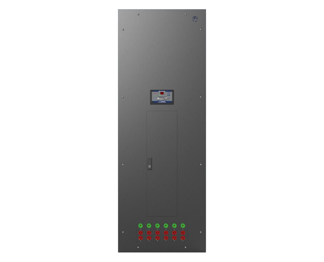
The Plus Series Isolated Power Panel (Model IPP-P) is the standard panel for most installations.The Model IPP-P Panel is typically designed to provide 120v isolated power to the circuits within a single operating or patient procedure room.
For special applications, the system can be configured to provide high-volt isolated output, such as 208V, 220V, or 240V. It is recommended that each Operating Room be designed with a minimum of two 7.5 kVA Isolated Power Panels powered on the Critical Branch on separate transfer switches.
Included with 120V Operating Room Isolated Power Supply Panel
- Hospital grade isolation transformer
- Line Isolation Monitor (LIM)
- Up to 16 circuit panelboard
- Room reference ground bus
- Concealed hinge door-in-door design
- Optional accessory device plate
Panel Sizing
|
kVA Size |
Back Box Size |
|
3 |
|
|
5 |
|
|
7.5 |
|
|
10 |
Features
All Plus Series Model IPP-P Isolated Power Supply Systems include:
Hospital Grade Isolation Transformer:
- Standard sizes range from 3 to 10 kVA for typical equipment
- Primary voltages: 480, 277, 240, 208, and 120* VAC
- Secondary voltages: 240, 208, and 120** VAC
- Low leakage, electrostatically shielded primary and secondary windings
- 220°C Class R Insulation
- Clamped and bolted design with anti-vibration mounting bushings for quiet operation
- Designed and built in accordance with UL and CSA Standards
- 50Hz available (optional)
*120V primary not available for IPD and IPL panels
**120V secondary not available for IPL panels
SafeDetec® Isolation Monitor (LIM):
- State-of-the-art all digital Total Hazard Current measurement
- Advanved filtering and noise suppression for improved accuracy and reliability
- High contrast 40-character LED display for better visibility and viewing angle
- Universal 120-240 VAC power input allows LIMs to be directly Interchanged from 120V to 208V/240V laser panels without changing the internal jumper or switch settings
- Additional parameters can be displayed on the user interface for more advanced troubleshooting, such as L1 and L2 line-to-ground voltages, insulation resistance, and insulation capacitance
- Increased memory allows more log entries and a longer history of LIM data
Interior Chassis:
- Interior chassis built to order, fully assembled in the factory, and 100% tested
- Primary main circuit breaker
- Up to 16 factory installed 120V, two-pole, bolt-on branch circuit breakers*
- Copper ground bus
- Terminal strip for connecting Remote Annunciator(s)
- Customer may specify standard circuit breakers from Eaton, GE, Siemens or Schneider Electric for consistent coordination or to maintain facility standard*
Enclosure and Trim:
- Heavy-duty galvanized steel back box designed for flush mounting; can be shipped ahead of interior during rough-in
- Stainless steel front trim panel with fully hidden hinged, door-in-door construction reduces damage and potential injuries during installation, testing, and maintenance*
- Surface mounting options available
Installation
- If the Isolated Power Panel is not installed inside the patient/procedure room, National Electric Code requires that a Remote Annunciator be installed so that it is “conspicuously visible” in the area served.
- Special low leakage wire should always be used for the powered conductors of branch circuit wiring. XPLE type insulation such as XHHW-2 wire is recommended with a dielectric constant of less than 3.5. Standard type insulation such as THHN is appropriate for the incoming primary and the ground wires only.
- The NEC (Article 517.160) requires secondary circuits to be colored brown and orange, with a distinctive stripe in a contrasting color. The brown wire is connected to the L2 bus and the hot side (brass screw) of a standard NEMA receptacle. The orange wire, L1 is connected to the silver screw where neutral would be connected. Polarity should be maintained throughout the installation.
- Conduit runs for branch circuits should be as short and direct as possible to minimize accumulated leakage current in the circuit conductors. Generally, 400‐450 feet is the maximum recommended cumulative length of all branch conductors from a single transformer. Avoid unnecessary bends and junctions.
- Do not use pulling compounds to lubricate inside of the conduit. This will break down the insulation properties and raise leakage current. A dry talc powder may be used. It is typical to use conduit with a slightly larger diameter to ease pulling and avoid damage to wire insulation. An interior coating of PVC may also be used.
- Isolated power circuits must be kept separate from other circuits. Do not share the conduit or raceway with non‐isolated circuits, or isolated circuits from another system.
- Each receptacle and equipment grounding connector must be connected back to Reference Ground Bus inside Isolation Panel to maintain Equipotential grounding system. If multiple panels serve the same space, they must be bonded together.
Certifications
PG LifeLink Isolated Power equipment is designed, built, and tested in accordance with the following:
- UL 1047, UL 1022, UL 50
- CSA C22.1 Part 1, and CSA C22.2 No. 204
- IBC (2012), AC156 (2010), ASCE 7-10
- OSHPD (State of California), OSP-0210-10
PG LifeLink Isolated Power Systems UL Certification document
PG LifeLink Isolated Power Panel IBC 2018 Seismic Certification - For more information, click here.
*Only PG LifeLink offers this as standard
*Seismic Certification is in process for Plus Series. Slim panels are available upon request.
a. is the standard panel for most installations. The Model IPP-P Panel is typically designed to provide 120v isolated power to the circuits within a single operating or patient procedure room. For special applications, 120V Operating Room Isolated Power Supply the system can be configured to provide high volt isolated output such as 208V, 220V, or 240V. It is recommended that each Operating Room be designed with a minimum of two 7.5 kVA Isolated Power Panels powered on Critical Branch on separate transfer switches.
or Contact Us at 800.287.4123